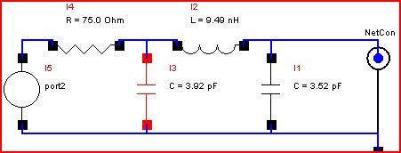
3.1 Auto Matching a single wave form
The automatic matching of circuits works by adding components to the port branch that allow the user to target one of two matching goals one being return loss match and the other being a noise match the later is provided that a S-parameter file with noise is in the schematic.
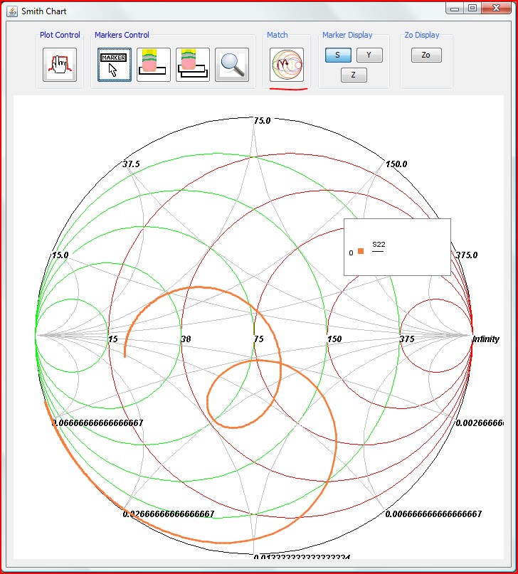
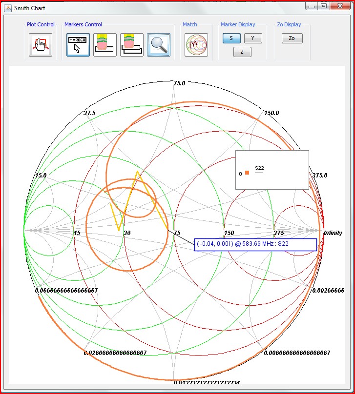
From the Smith Chart window click on the match button highlighted below.
The next several steps will result in a match to the optimum return loss.
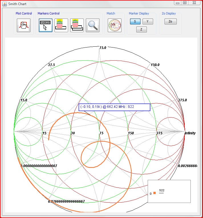
Step 1. Add marker at the data point, to find the point of interest utilize the magnifying glass to view the marker before selecting.
then click the point when you find the one you want.
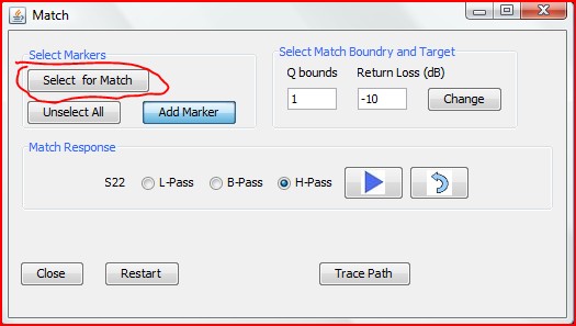
Step 2. Select marker to match
click on the marker you just added and it will turn blue.
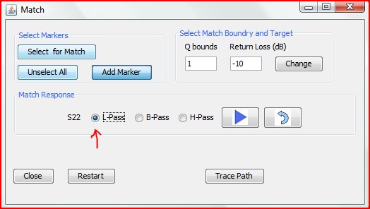
Step 3. Select the frequency response of the matching circuit
The options are :
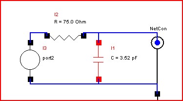
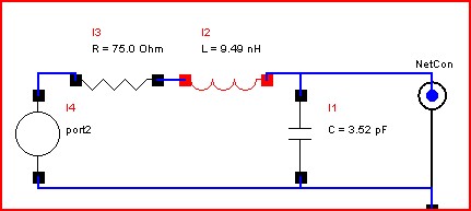
L-pass for low-pass match (shunt C series L)
H-pass for high-pass match (shunt L and series C)
B-pass for band-pass match which alternates between high and low pass
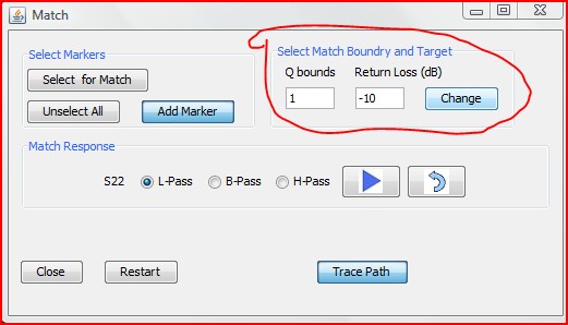
Step 4. Define the match target return loss and matching element Q bounds criteria
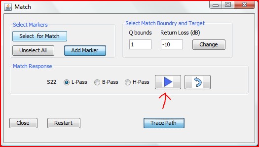
Step 5. Click the forward arrow to add matching components
To display on the Smith Chart the path that the matching took click Trace Path button to show the path the match took
Stop when you want or if you met the target criteria it will stop automatically.